Quantum Artifact
9 minutes to read
We are given the following Python source code that encodes the flag:
from qiskit import *
import qiskit.qasm2

flag = open('flag.txt', 'rb').read()
secret = ''.join("{0:08b}".format(c) for c in flag)
circuit = QuantumCircuit(len(secret)+1, len(secret))

circuit.h(range(len(secret)))
circuit.x(len(secret))
circuit.h(len(secret))

circuit.barrier()

for ii, yesno in enumerate(reversed(secret)):
    if yesno == '1':
        circuit.cx(ii, len(secret))

circuit.barrier()

circuit.h(range(len(secret)))
circuit.barrier()
circuit.measure(range(len(secret)), range(len(secret)))

qasm_code = qiskit.qasm2.dumps(circuit)

# Write the OpenQASM code to a file
with open('challenge_circuit.qasm', 'w') as file:
    file.write(qasm_code)
We are also given the quantum circuit serialized as challenge_circuit.qasm.
Source code analysis
As can be seen, the quantum circuit consists of several qbit registers, specifically, one more than the length of the flag in binary, and classical bit registers, exactly the length of the flag in binary:
flag = open('flag.txt', 'rb').read()
secret = ''.join("{0:08b}".format(c) for c in flag)
circuit = QuantumCircuit(len(secret)+1, len(secret))
We can check this by importing the quantum circuit and looking at some attributes:
$ python3 -q
>>> from qiskit import QuantumCircuit
>>>
>>> circuit = QuantumCircuit.from_qasm_file('challenge_circuit.qasm')
>>>
>>> circuit.num_qubits
233
>>> circuit.num_clbits
232
So we know that the flag is composed of 232 bits. The server adds a Hadamard gate to all these flag qbits:
circuit.h(range(len(secret)))
Then, the server adds a Pauli X gate and a Hadamard gate to the last qbit:
circuit.x(len(secret))
circuit.h(len(secret))
Here, the server adds a barrier to separate stages (nothing happens in the quantum circuit, it is just to improve readability):
circuit.barrier()
After that, the server starts encoding the bits of the flag in the quantum circuit:
for ii, yesno in enumerate(reversed(secret)):
    if yesno == '1':
        circuit.cx(ii, len(secret))
As can be seen, the bits are iterated in reverse order, and if the bit is 1, the server adds a CX gate (controlled X, also known as CNOT) between the corresponding qbit (control) of the flag and the last qbit (target).
After a second barrier, the server adds another Hadamard gate to all flag qbits:
circuit.barrier()

circuit.h(range(len(secret)))
Finally, after a third barrier, the server adds measurements to read the value of the flag qbits and write them to the corresponding classical bit registers:
circuit.barrier()
circuit.measure(range(len(secret)), range(len(secret)))
Solution
There are two ways to solve this challenge:
The easy way
Even if we know nothing about quantum computing, we know that there is a CX gate whenever the flag bit is 1. Therefore, we can take a look at the instruction of the circuit:
>>> print('\n'.join(map(str, circuit.get_instructions('cx'))))
CircuitInstruction(operation=Instruction(name='cx', num_qubits=2, num_clbits=0, params=[]), qubits=(<Qubit register=(233, "q"), index=0>, <Qubit register=(233, "q"), index=232>), clbits=())
CircuitInstruction(operation=Instruction(name='cx', num_qubits=2, num_clbits=0, params=[]), qubits=(<Qubit register=(233, "q"), index=2>, <Qubit register=(233, "q"), index=232>), clbits=())
CircuitInstruction(operation=Instruction(name='cx', num_qubits=2, num_clbits=0, params=[]), qubits=(<Qubit register=(233, "q"), index=3>, <Qubit register=(233, "q"), index=232>), clbits=())
...
CircuitInstruction(operation=Instruction(name='cx', num_qubits=2, num_clbits=0, params=[]), qubits=(<Qubit register=(233, "q"), index=222>, <Qubit register=(233, "q"), index=232>), clbits=())
CircuitInstruction(operation=Instruction(name='cx', num_qubits=2, num_clbits=0, params=[]), qubits=(<Qubit register=(233, "q"), index=227>, <Qubit register=(233, "q"), index=232>), clbits=())
CircuitInstruction(operation=Instruction(name='cx', num_qubits=2, num_clbits=0, params=[]), qubits=(<Qubit register=(233, "q"), index=230>, <Qubit register=(233, "q"), index=232>), clbits=())
Notice that the CX gate involves two qbits, the control qbit and the target qbit. We are interested in taking the index of the control qbit, which can be done as follows:
>>> [i.qubits[0]._index for i in circuit.get_instructions('cx')]
[0, 2, 3, 4, 5, 6, 8, 9, 12, 13, 20, 21, 22, 28, 29, 35, 37, 38, 40, 41, 42, 43, 44, 46, 48, 49, 52, 53, 56, 58, 59, 61, 62, 68, 69, 72, 73, 76, 77, 78, 80, 81, 82, 83, 84, 86, 90, 91, 93, 94, 98, 99, 101, 102, 104, 108, 109, 114, 116, 117, 118, 120, 121, 124, 125, 126, 128, 129, 130, 131, 132, 134, 136, 137, 140, 141, 142, 144, 148, 149, 152, 153, 154, 155, 156, 158, 160, 161, 164, 165, 169, 172, 173, 174, 176, 177, 180, 181, 187, 189, 190, 194, 196, 197, 198, 200, 201, 203, 204, 205, 206, 209, 214, 218, 220, 222, 227, 230]
Now we are only left with setting a 1 or a 0 depending on whether the flag index appears in the above list or not:
>>> ''.join(map(str, (int(x in [i.qubits[0]._index for i in circuit.get_instructions('cx')]) for x in reversed(range(circuit.num_qubits - 1)))))
'0100100001010100010000100111101101110100011010000011001101110010001100110101111100110001011100110101111101110011011101000011000101101100011011000101111101110011001100000110110100110011010111110110100000110000011100000011001101111101'
Next, we just convert the above binary string to bytes and done, but we have learnt nothing about quantum computing.
Quantum computing background
I’ll give some background knowledge about quantum computing and quantum gates:
In quantum computing, qbits don’t have a certain value, they have a superposition state. It means that they can have any value, until the qbit is measured. Once a qbit is observed, it collapses to a value (
0or1) and it cannot be changed. And this happens with some probability, that can be expressed as, where and represent the probability of collapsing to 0or1, thusA Hadamard gate (H) produces a “change of basis”:
Measuring a qbit that has been transformed by a Hadamard gate has 50% chance of collapsing to
0or1The Pauli gate X behaves as follows:
In particular
The CX gate involves two qbits: the control qbit and the target qbit. If the control qbit is
the operation X is performed on the target qbit. In particular One direct application of the CX gate (also known as CNOT) is the Bell state, which is a form of quantum entanglement:
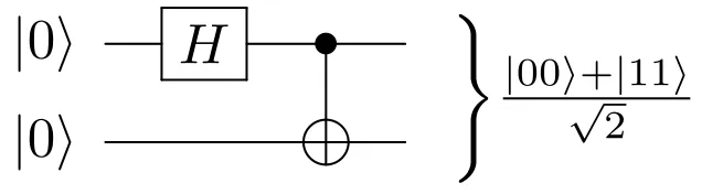
The previous circuit has 3 different states:
Initial state:
After the H gate:
After the CX gate:
At this point, both qbits are entangled, which means that if we measure a 0 on the first qbit, the second qbit will have a 0 as well. The same happens for a value of 1. Both qbits will collapse to the same state.
The good way
First of all, let’s take a look at the quantum circuit; we can simply print it (I’ll remove almost all qbits and instructions because the quantum circuit is huge):
>>> print(circuit)
       ┌───┐      ░                           ░ ┌───┐ ░ ┌─┐
  q_0: ┤ H ├──────░───■─────── ... ───────────░─┤ H ├─░─┤M├───── ... ───
       ├───┤      ░   │                       ░ ├───┤ ░ └╥┘┌─┐
  q_1: ┤ H ├──────░───┼─────── ... ───────────░─┤ H ├─░──╫─┤M├── ... ───
       ├───┤      ░   │                       ░ ├───┤ ░  ║ └╥┘

...

       ├───┤      ░   │    │         │    │   ░ ├───┤ ░  ║  ║        ┌─┐
q_231: ┤ H ├──────░───┼────┼── ... ──┼────┼───░─┤ H ├─░──╫──╫─── ... ┤M├
       ├───┤┌───┐ ░ ┌─┴─┐┌─┴─┐     ┌─┴─┐┌─┴─┐ ░ └───┘ ░  ║  ║        └╥┘
q_232: ┤ X ├┤ H ├─░─┤ X ├┤ X ├ ... ┤ X ├┤ X ├─░───────░──╫──╫─── ... ─╫─
       └───┘└───┘ ░ └───┘└───┘     └───┘└───┘ ░       ░  ║  ║         ║
c: 232/═══════════════════════ ... ══════════════════════╩══╩═══ ... ═╩═
                                                         0  1        231
The quantum circuit looks overwhelming, but we can just focus on a single flag qbit and the last qbit (q_232). There must be a way to tell if the flag qbit encodes a logical 0 or a 1 by looking at the measurements when simulating the circuit.
Indeed, let’s assume that we are analyzing a qbit that encodes a 1. Let
- Initial state:
Now, we apply the Hadamard gate on the flag qbit and the X gate on the last qbit:
- After H and X:
Next, we apply the Hadamard gate on the last qbit:
- After H:
- Now, there is a CX gate since we have assume that:
- Finally, we apply a Hadamard gate on the flag qbit:
So, this is the evolution of a flag qbit that encodes a 1 and the last qbit:
In case, the flag qbit encodes a 0, we simply skip the CX gate, so the final state is
Therefore, this is the evolution of a flag qbit that encodes a 0 and the last qbit:
As can be seen, the flag qbit ends up with a state of 0 and a state of 1, with 100% probability. Therefore, we will see these results in the measurements once we run the circuit with all qbits initialized with
We could have initialized the qbits at
In order to run the circuit, we just need to use the following instructions:
>>> from qiskit_aer import AerSimulator
>>>
>>> simulator = AerSimulator()
>>> result = simulator.run(circuit).result()
Now, we can see the results with get_counts:
>>> result.get_counts()
{'0100100001010100010000100111101101110100011010000011001101110010001100110101111100110001011100110101111101110011011101000011000101101100011011000101111101110011001100000110110100110011010111110110100000110000011100000011001101111101': 1024}
The above binary string means that qbit q_231 has collapsed to a 0, qbit q_230 has collapsed to a 1 and so on until q_0 (I don’t know why it appears in reverse order, but it cancels the initial reversed function on the flag bits). Notice that this is the same binary string we got earlier. Now, we only need to take the above binary string and convert it to bytes.
There is another function that allows us to get the binary string in hexadecimal format, which is easier to convert to bytes:
>>> result.data()
{'counts': {'0x4854427b74683372335f31735f7374316c6c5f73306d335f683070337d': 1024}}
Flag
And here is the flag:
>>> bytes.fromhex(list(result.data().get('counts').keys())[0][2:])
b'HTB{th3r3_1s_st1ll_s0m3_h0p3}'